This quick reference page provides a summary of the specifications of this topology. For a complete reference including installation details, please refer to the Advanced Router Pod Planning and Installation Guide
| Topology | Supports | Documentation |
|---|---|---|

|
CCNA and CCNP 3.x | Planning and Installation Guide |

Lab devices are part of the topology and users can interact with them either directly through the console or network.
Hardware compatibility with NETLAB+ does not guarantee the compatibility of labs. Please check the Academy curriculum, NDG pod guides, and lab support pages for specific hardware and IOS requirements.
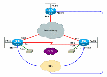
The Advanced Router Pod contains three routers, R1, R2 and R3.
Other equipment may work if it is supported by NETLAB+ and can meet the minimum requirements for feature sets, interfaces, IOS, RAM, and Flash
| Devices | Ethernet | Serial | BRI | PRI | AUX/External Modem |
|---|---|---|---|---|---|
| R1 | 1 | 2 | 1 | 1 | |
| R2 | 1 | 1 | Optional | 1 (Recommended) | Optional |
| R3 | 1 | 2 | 1 | 1 |
The NETLAB+ interface name translation feature is supported on this pod type. This may influence the selection of modular interface cards and slot placement within the router. Please review the expected interface names for each router.
The Ethernet interface must be a built-in interface, which is capable of activation from the ROM monitor mode. All NETLAB+ supported routers have at least one Ethernet interface that meets this requirement.
Serial interfaces may be built-in, or provided by modular interface cards such as the WIC-2AS or WIC-2T. Serial connections between routers require the appropriate serial cables. You can use DTE and DCE cables back-to-back, or special cables that provide both DTE and DCE in one cable (available from SIGMAnet).
Be sure to match your router and Adtran Atlas BRI and PRI interface types according to you local requirements (i.e. BRI vs. S/T, T1/PRI vs. E1/PRA).
R1 and R3 communicate with the PSTN using external modems (sold separately).
The Advanced Router Pod utilizes an Adtran Atlas 550 to emulate functions normally obtained from a network service provider. The Atlas 550 is statically configured and always powered on. Lab users do not interact with the Atlas management console.
Per the following table, insert the following cards into following Atlas 550 chassis slots.
| Slot | Module |
|---|---|
| SLOT 1 | Dual Nx56/64 V.35 Module |
| SLOT 2 | Dual Nx56/64 V.35 Module |
| SLOT 3 | FXS Module |
| SLOT 4 | ISDN BRI Module or S/T Module (as required) |
| NETWORK 1 | ISDN PRI Module |
Per the following table, connect the router serial interfaces to the Atlas 550 and create 6 permanent virtual circuits using the Atlas management interface.
| Router | Local Interface |
Local DLCI | Adtran | Adtran | Maps to Remote Router |
Interface |
|---|---|---|---|---|---|---|
| R1 | Serial 0/0 | 102 | 1/1 | 1/2 | R2 | Serial 0/0 |
| R1 | Serial 0/0 | 103 | 1/1 | 2/1 | R3 | Serial 0/0 |
| R2 | Serial 0/0 | 201 | 1/2 | 1/1 | R1 | Serial 0/0 |
| R2 | Serial 0/0 | 203 | 1/2 | 2/1 | R3 | Serial 0/0 |
| R3 | Serial 0/0 | 301 | 2/1 | 1/1 | R1 | Serial 0/0 |
| R3 | Serial 0/0 | 302 | 2/1 | 1/2 | R2 | Serial 0/0 |
Using the following table, connect R1 and R3 to external modems, and configure the phone numbers on the Atlas 550. R2 may be optionally connected to the third FXS port.
| Router | Port | Atlas 550(FXS) | Phone Number |
|---|---|---|---|
| R1 | AUX | 3/1 | 5556001 |
| R3 | AUX | 3/2 | 5556002 |
| R2 (Optional) | AUX | 3/3 | 5556003 |
Per the following table, connect your router BRI (or S/T> interfaces to the Atlas 550.
| Router | Port | Atlas 550(BRI) | SPID |
|---|---|---|---|
| R1 | BRI | 4/1 |
SPID1: 51055510000001 5551000 SPID2: 51055510010001 5551001 |
| R3 | BRI | 4/2 |
SPID1: 51055520000001 5552000 SPID2: 51055520010001 5552001 |
| R2 (Optional) | BRI | 4/3 |
SPID1: 51055530000001 5553000 SPID2: 51055530010001 5553001 |
To implement PRI, connect router R2's PRI interface to the Atlas 550 PRI interface.
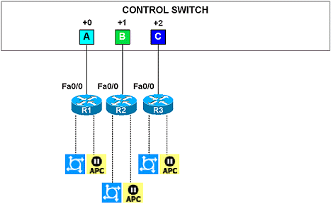
Control devices provide internal connectivity, console access, and managed power. Control devices are dynamically managed by NETLAB+ and are not accessible or configurable by end users.
| Control Device Resource | Quantity Required |
|---|---|
| Control Switch | 3 Consecutive Ports |
| Access Server | 3 Lines |
| Switched Outlet Devices | 3 Outlets |
